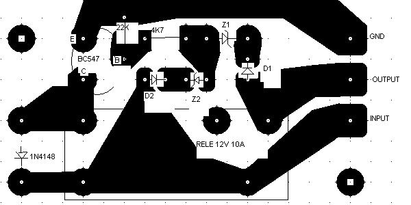
In the power supplies that can take batteries I put this circuit to protect the battery from fully discharged.
It stops the load when the voltage drops below 11.4 V and it reconnects it when the mains power supply gives 13 V.
This difference prevents from oscillating the relay when the power output disconnected and the battery voltage increase.
For these voltages the D1 is 1N4148 and D2 is two 1N4148 in series. The Z2 is 11V and Z1 is 10V zeners.
If you need different voltages you can change the zeners or put more or less diodes.
For smaller voltage steps you can use BAT85 instead of 1N4148.
For example if you use BAT85 for D1 the load will be disconnected at about 11 V.
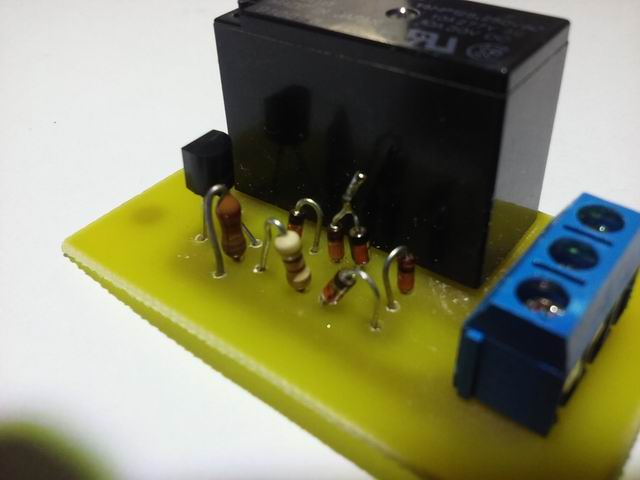
The transistor is a BC547 but any similar NPN is suitable. The relay is a 12V 10A.
You can easy convert it for 24 V usage.
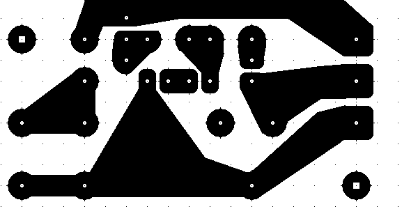
In the photo I put one of the two D2 in series with Z2. The PCB is done with paint.